
User’s manual
Introduction……………………………………………………………..…….2
Drivers installation………………………………………………….………....2
Features of DMX PIPE…….………………………………...……………….3
Package contents..…………………………………………………………….4
Connection of the DMX512 cable …………………………………………....4
Linking of the DMX512 units.…………..………………………………….....6
Technical
specification…..…………………………………………………....7
DMX PIPE enables connection of the DMX512 data bus using USB. It is possible both to export data and to import data from an external device. The number of bites in a packet sent via data bus is not limited. It is therefore possible to use all 512 channels or a different number of them according to the program used.
Installation of drivers for Windows XP and Windows 2000
The drivers can be found in Drivers\WinXP or Drivers\Win2000 directory. For installation execute file „CDM 2.02.04.exe“. Installation will run automatically in the background and when the installation is complete, information that „FTDI CDM Drivers have been successfully installed“, will appear. After installation the connected DMX PIPE interface will be automatically detected.
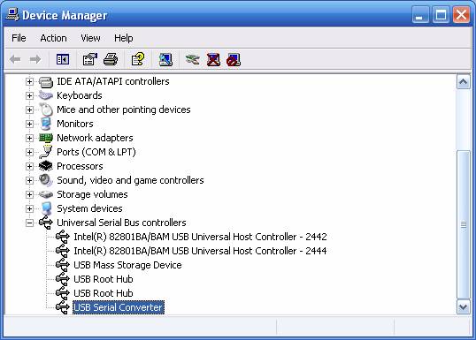
Successfully installed hardware can be found in the “Device Manager” as “USB Serial Converter”.
Installation can also be done by ”Control Panel“ using “Add hardware” item. In this case open firstly “CDM 2.02.04 WHQL Certified.zip” file into your chosen directory and then choose this directory when asked for the placement of the driver files. This way not only the control device named as “USB Serial Converter”, but also the “WDM driver” (for direct access to DMX PIPE interface) can be installed. The device should function well with both types of drivers.
· Full 512 channels
· Export/Import via DMX512 data bus
· Full speed of DMX512
· USB 2.0 compatible
· Low consumption from USB
· Working temperature range -40°C to 85°C
Interface DMX PIPE with cable for USB connection
CD with control devices and control programs
Manual for the DMX PIPE usage
Manual for Music Visualization
Description of
the programs included
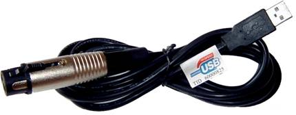
The following picture shows how to connect the cable. The grounding outlet of the XLR connector is not used for grounding. Therefore do not connect shield to the metal connector cover, it can cause short circuit or unexpected behavior. Shield should be connected to pin number 1.
Connection of the DMX512 cable
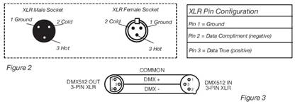
For the connection of longer cables, it is necessary to use a terminator (for impendent adaptation of the wiring) to the end of the wiring. Terminator is 120 Ohms resistance, ¼ W connected between pins 2 and 3 on the XLR connector socket (to DATA+ and DATA-). Resistance can be soldered in to the XLR socket and connected to the last DMX unit. This way the likelihood of the potential unexpected behavior of units is lowered.
Some producers use 5-pin XLR DMX connector for data transfer instead of a 3-pin one. Standard 5-pin XLR connector can be implemented into a 3-pin one using cable adapter. Connection of pins for a 5 or 3-pin XLR connector is shown in the following table.
|
Conductor |
3-Pin XLR Female (Out) |
5-Pin XLR Male (In) |
|
Shield / Ground |
Pin 1 |
Pin 1 |
|
Data Compliment (- signal) |
Pin 2 |
Pin 2 |
|
Data True (+ signal) |
Pin 3 |
Pin 3 |
|
Not Used |
|
Do Not Use |
|
Not Used |
|
Do Not Use |
Connection of the XLR connector
Any hardware working with the DMX512 protocol can be connected to the DMX PIPE. Interconnection of the individual modules is done as a data bus, where a terminator has to be connected to the last unit. Do not connect the device in a star or other unsuitable topology. The control of units is independent and their address is set up according to a table provided by the producer.
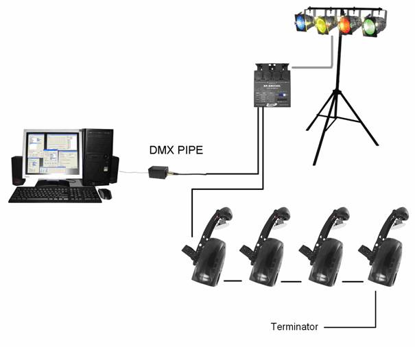
Scheme of connecting DMX512 units
Supply of the module from USB
Power take-off 70 mA
Cable length 1.6 m
Weight 0.1 kg
Working position any safe position
Output DMX512 (EIA-485)
Guarantee 24 months